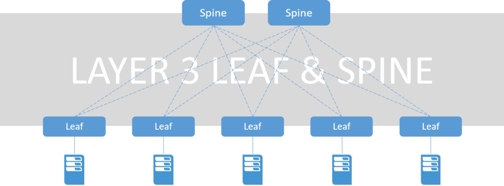
Semakin meningkatnya penggunaan teknologi virtualisasi server berdampak pada berubahnya traffic patterns dan volume traffic pada network datacenter. Model Datacenter terdahulu yang menggunakan hirarki three-tier model (Access, Aggregation, Core) sudah tidak optimal untuk mensupport traffic flow East-West yang berat.
Desain Leaf Spine menawarkan kemampuan yang lebih baik dari pada three-tier model, seperti scaling yang lebih mudah dan performa yang lebih baik. Penggunaan layer 3 pada desain Leaf Spine dapat mengeliminasi kebutuhan Layer 2 loop teknologi seperti spanning-tree.
Pada tulisan kali ini kita akan mencoba membangun network L3LS (Layer 3 Leaf Spine) sederhana menggunakan device Arista, Layer 3 yang akan digunakan adalah routing protocol eBGP untuk bertukar routes yang di learn di masing-masing device. Mungkin ada yang bertanya “Mengapa tidak memakai routing protocol lain seperti OSPF/IS-IS?”. Ini dikarenakan eBGP lebih less controller dari pada OSPF/IS-IS serta lebih memudahkan kita dalam mengontrol prefix-prefix yang ingin di advertise atau di receive dari node lain.
LAB Test
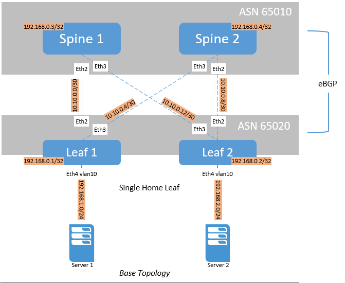
Berikut software release dan base topology yang digunakan :
- GNS3 version 2.1
- Arista vEOS 4.20.1F
Topologi diatas menggunakan 1 ASN pada group router Spine dan 1 ASN pada group router Leaf (Common Spine ASN – Common Leaf ASN), ada opsi lain yang bisa digunakan yaitu Common Spine ASN- Discrete Leaf ASN. Dari kedua desain tersebut Common Spine ASN – Common Leaf ASN lebih simple dalam deployment, operations, dan automation tasks. Perlu diingat bahwa jika menggunakan desain Common Spine ASN- Discrete Leaf ASN AS Number private yang dapat digunakan adalah (64512 to 65534).
Setelah topologi dibuat lakukan konfigurasi interface pada setiap spine dan leaf seperti berikut :
Leaf 1
|
1 2 3 4 5 6 7 8 9 10 11 12 13 14 15 16 17 18 19 20 21 22 23 24 25 26 27 28 |
leaf-1#show running-config ---<output omitted>--- interface Ethernet2 description to-spine-1 mtu 9214 logging event link-status no switchport ip address 10.10.0.1/30 arp timeout 900 ! interface Ethernet3 description to-spine-2 mtu 9214 logging event link-status no switchport ip address 10.10.0.5/30 arp timeout 900 ! interface Ethernet4 switchport access vlan 10 ! interface Loopback0 description router-id ip address 192.168.0.1/32 ! interface Vlan10 ip address 192.168.1.1/24 ! |
Leaf 2
|
1 2 3 4 5 6 7 8 9 10 11 12 13 14 15 16 17 18 19 20 21 22 23 24 25 26 27 28 |
Leaf-2#show running-config ---<output omitted>--- interface Ethernet2 description to-spine-2 mtu 9214 logging event link-status no switchport ip address 10.10.0.9/30 arp timeout 900 ! interface Ethernet3 description to-spine-1 mtu 9214 logging event link-status no switchport ip address 10.10.0.13/30 arp timeout 900 ! interface Ethernet4 switchport access vlan 10 ! interface Loopback0 description router-id ip address 192.168.0.2/32 ! interface Vlan10 ip address 192.168.1.1/24 ! |
Spine 1
|
1 2 3 4 5 6 7 8 9 10 11 12 13 14 15 16 17 18 19 20 21 22 |
spine-1#sh running-config ---<output omitted>--- interface Ethernet2 description to-leaf-1 mtu 9214 logging event link-status no switchport ip address 10.10.0.2/30 arp timeout 900 ! interface Ethernet3 description to-leaf-2 mtu 9214 logging event link-status no switchport ip address 10.10.0.14/30 arp timeout 900 ! interface Loopback0 description router-id ip address 192.168.0.3/32 ! |
Spine 2
|
1 2 3 4 5 6 7 8 9 10 11 12 13 14 15 16 17 18 19 20 21 22 |
spine-2#show running-config ---<output omitted>--- interface Ethernet2 description to-leaf-2 mtu 9214 logging event link-status no switchport ip address 10.10.0.10/30 arp timeout 900 ! interface Ethernet3 description to-leaf-1 mtu 9214 logging event link-status no switchport ip address 10.10.0.6/30 arp timeout 900 ! interface Loopback0 description router-id ip address 192.168.0.4/32 ! |
Test point-to-point reachability pada setiap switch menggunakan PING command, setelah semua switch telah sukses terkoneksi selanjutnya melakukan konfigurasi BGP pada keempat switch seperti berikut :
Leaf 1
|
1 2 3 4 5 6 7 8 9 10 11 12 13 14 15 16 17 |
leaf-1>ena leaf-1#configure terminal leaf-1(config)#router bgp 65020 leaf-1(config-router-bgp)#show active router bgp 65020 router-id 192.168.0.1 distance bgp 20 200 200 maximum-paths 2 neighbor to-spine peer-group neighbor to-spine remote-as 65010 neighbor to-spine allowas-in 1 neighbor to-spine maximum-routes 12000 neighbor 10.10.0.2 peer-group to-spine neighbor 10.10.0.6 peer-group to-spine network 192.168.0.1/32 redistribute connected leaf-1(config-router-bgp)# |
Leaf 2
|
1 2 3 4 5 6 7 8 9 10 11 12 13 14 15 16 17 |
Leaf-2>ena Leaf-2#configure terminal Leaf-2(config)#router bgp 65020 Leaf-2(config-router-bgp)#show active router bgp 65020 router-id 192.168.0.2 distance bgp 20 200 200 maximum-paths 2 neighbor to-spine peer-group neighbor to-spine remote-as 65010 neighbor to-spine allowas-in 1 neighbor to-spine maximum-routes 12000 neighbor 10.10.0.10 peer-group to-spine neighbor 10.10.0.14 peer-group to-spine network 192.168.0.2/32 redistribute connected Leaf-2(config-router-bgp)# |
Spine 1
|
1 2 3 4 5 6 7 8 9 10 11 12 13 14 15 |
spine-1>ena spine-1#configure terminal spine-1(config)#router bgp 65010 spine-1(config-router-bgp)#show active router bgp 65010 router-id 192.168.0.3 distance bgp 20 200 200 maximum-paths 2 neighbor to-leaf peer-group neighbor to-leaf remote-as 65020 neighbor to-leaf maximum-routes 12000 neighbor 10.10.0.1 peer-group to-leaf neighbor 10.10.0.13 peer-group to-leaf network 192.168.0.3/32 spine-1(config-router-bgp)# |
Spine 2
|
1 2 3 4 5 6 7 8 9 10 11 12 13 14 15 |
spine-2>ena spine-2#configure terminal spine-2(config)#router bgp 65010 spine-2(config-router-bgp)#show active router bgp 65010 router-id 192.168.0.4 distance bgp 20 200 200 maximum-paths 2 neighbor to-leaf peer-group neighbor to-leaf remote-as 65020 neighbor to-leaf maximum-routes 12000 neighbor 10.10.0.5 peer-group to-leaf neighbor 10.10.0.9 peer-group to-leaf network 192.168.0.4/32 spine-2(config-router-bgp)# |
Jika semua Switch telah dikonfigurasi, pastikan BGP peer antar switch sudah established dan menerima route dari switch lain dengan cara mem-verifikasi menggunakan perintah show ip bgp summary dan show ip route seperti berikut :
|
1 2 3 4 5 6 7 8 9 10 11 12 13 14 15 16 17 18 19 20 21 22 23 24 25 26 27 28 29 30 31 32 33 34 35 |
leaf-1#show ip bgp summary BGP summary information for VRF default Router identifier 192.168.0.1, local AS number 65020 Neighbor Status Codes: m - Under maintenance Neighbor V AS MsgRcvd MsgSent InQ OutQ Up/Down State PfxRcd PfxAcc 10.10.0.2 4 65010 64 65 0 0 00:58:57 Estab 4 4 10.10.0.6 4 65010 45 46 0 0 00:39:21 Estab 4 4 leaf-1#show ip route VRF: default Codes: C - connected, S - static, K - kernel, O - OSPF, IA - OSPF inter area, E1 - OSPF external type 1, E2 - OSPF external type 2, N1 - OSPF NSSA external type 1, N2 - OSPF NSSA external type2, B I - iBGP, B E - eBGP, R - RIP, I L1 - IS-IS level 1, I L2 - IS-IS level 2, O3 - OSPFv3, A B - BGP Aggregate, A O - OSPF Summary, NG - Nexthop Group Static Route, V - VXLAN Control Service, DH - Dhcp client installed default route Gateway of last resort is not set C 10.10.0.0/30 is directly connected, Ethernet2 C 10.10.0.4/30 is directly connected, Ethernet3 B E 10.10.0.8/30 [20/0] via 10.10.0.2, Ethernet2 B E 10.10.0.12/30 [20/0] via 10.10.0.6, Ethernet3 C 192.168.0.1/32 is directly connected, Loopback0 B E 192.168.0.2/32 [20/0] via 10.10.0.2, Ethernet2 via 10.10.0.6, Ethernet3 B E 192.168.0.3/32 [20/0] via 10.10.0.2, Ethernet2 B E 192.168.0.4/32 [20/0] via 10.10.0.6, Ethernet3 C 192.168.1.0/24 is directly connected, Vlan10 B E 192.168.2.0/24 [20/0] via 10.10.0.2, Ethernet2 via 10.10.0.6, Ethernet3 leaf-1# |
Terakhir lakukan pengetesan Ping antar server, hasilnya bisa dipastikan sever dapat melakukan ping satu sama lain:
|
1 2 3 4 5 6 7 8 9 10 11 12 13 14 |
root@Server1:~# ping 192.168.2.2 PING 192.168.2.2 (192.168.2.2) 56(84) bytes of data. 64 bytes from 192.168.2.2: icmp_seq=1 ttl=61 time=100 ms 64 bytes from 192.168.2.2: icmp_seq=2 ttl=61 time=67.2 ms 64 bytes from 192.168.2.2: icmp_seq=3 ttl=61 time=65.0 ms 64 bytes from 192.168.2.2: icmp_seq=4 ttl=61 time=67.1 ms 64 bytes from 192.168.2.2: icmp_seq=5 ttl=61 time=69.0 ms 64 bytes from 192.168.2.2: icmp_seq=6 ttl=61 time=80.2 ms 64 bytes from 192.168.2.2: icmp_seq=7 ttl=61 time=83.7 ms ^C --- 192.168.2.2 ping statistics --- 7 packets transmitted, 7 received, 0% packet loss, time 6007ms rtt min/avg/max/mdev = 65.005/76.148/100.614/12.008 ms root@Server1:~# |
Sekian untuk pembahasan sederhana mengenai konfigurasi layer 3 leaf spine pada Arista, untuk postingan selanjutnya saya akan membahas mengenai network overlay yang berjalan di datacenter menggunakan device arista dengan memanfaatkan hasil konfigurasi L3LS pada posting ini.
Terima Kasih,
Network Telco Engineer – SDN/NFV Enthusiast


Komentar