Artikel ini akan membahas bagaimana mengkonfigurasi Network Virtualization pada Arista menggunakan VXLAN . Nantinya hasil dari konfigurasi ini akan membentuk suatu komunikasi Layer2 antar server melewati Layer3 Network (Underlay).
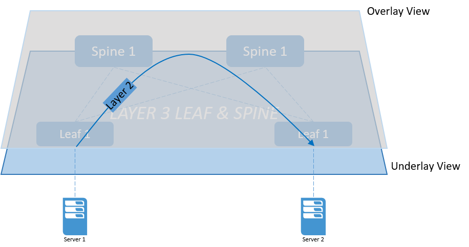
Sedikit menjelaskan tentang perbedaan istilah Overlay dan Underlay Network, untuk lebih mudah memahami mari perhatikan gambar berikut :
Pada gambar diatas terdapat Layer 3 Network dengan 2 Leaf dan 2 Spine, setiap Leaf terkoneksi dengan satu server, ketika server 1 ingin berkomunikasi dengan server 2, maka dari prepektif server 1 dia hanya terkoneksi dengan server 2 secara point-to-point.
Ada beberapa macam Teknologi Overlay Network seperti VXLAN, NVGRE, STT. Umumnya VXLAN digunakan pada datacenter yang sudah menerapkan overlay network technology. VXLAN (Virtual Extensible LAN) adalah standar enkapsulasi MAC di dalam IP protokol yang bisa digunakan untuk :
- Provide layer 2 conectivity antar server berbeda rack/POD
- Untuk Data Center Interconnect
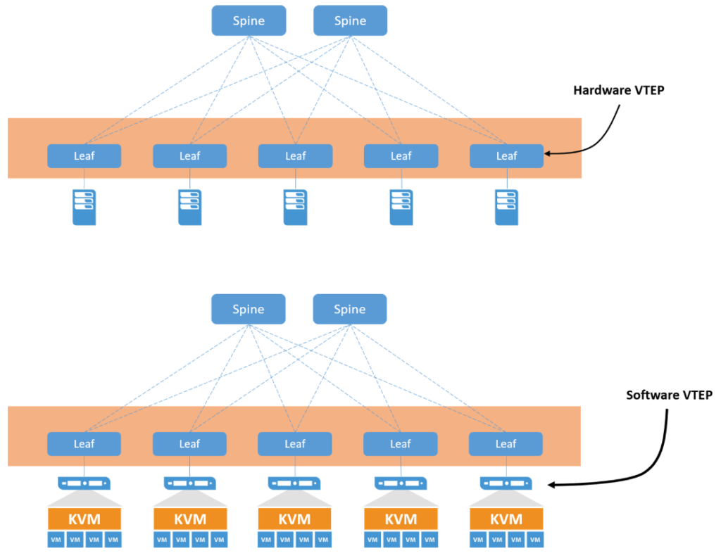
Enkapsulasi VXLAN dilakukan oleh Virtual Tunnel Endpoint (VTEP), terdapat dua jenis VTEP yaitu Software dan Hardware.
Software VTEP melakukan enkapsulasi pada level hypervisor contohnya OpenVswitch, VMware NSX sedangkan Hardware VTEP melakukan enkapsulasi pada Switch Fisik.
Control Plane pada VXLAN
Mekanisme Learn dan Flood BUM Traffic pada VXLAN dapat menggunakan 3 cara yaitu :
- Multicast
- Head End Replecation
- EVPN
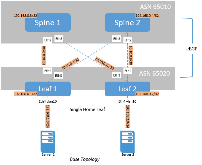
Pada konfigurasi kali ini kita akan menggunakan Head End Replication sebagai control plane pada VXLAN. Untuk topologi simulasi Lab akan memanfaatkan topologi yang telah dibuat pada artikel sebelumnya “Konfigurasi Layer 3 Leaf Spine Pada Arista Network”
Leaf 1
|
1 2 3 4 5 6 7 8 9 10 11 12 13 14 15 16 17 18 19 20 21 22 23 24 25 26 27 28 29 30 31 32 33 34 35 36 37 38 39 40 41 42 43 44 45 46 47 48 49 50 51 52 53 54 55 56 57 58 59 60 61 62 63 64 65 66 67 68 69 70 71 72 73 74 75 76 77 78 79 80 81 82 83 84 85 86 87 |
leaf-1#show running-config ! Command: show running-config ! device: leaf-1 (vEOS, EOS-4.20.1F) ! ! boot system flash:/vEOS-lab.swi ! transceiver qsfp default-mode 4x10G ! hostname leaf-1 ! spanning-tree mode mstp ! no aaa root ! vlan 10-11 ! vrf definition MGMT rd 0:65010 ! interface Ethernet1 ! interface Ethernet2 description to-spine-1 mtu 9214 logging event link-status no switchport ip address 10.10.0.1/30 arp timeout 900 ! interface Ethernet3 description to-spine-2 mtu 9214 logging event link-status no switchport ip address 10.10.0.5/30 arp timeout 900 ! interface Ethernet4 switchport access vlan 10 ! interface Ethernet5 ! interface Ethernet6 ! interface Ethernet7 ! interface Ethernet8 ! interface Ethernet9 ! interface Ethernet10 ! interface Ethernet11 ! interface Ethernet12 ! interface Loopback0 description router-id ip address 192.168.0.1/32 ! interface Management0 ! interface Management1 vrf forwarding MGMT ip address 10.0.2.5/24 ! interface Vlan10 description to-server2 ! ip routing no ip routing vrf MGMT ! router bgp 65020 router-id 192.168.0.1 distance bgp 20 200 200 maximum-paths 2 ecmp 2 neighbor to-spine peer-group neighbor to-spine remote-as 65010 neighbor to-spine allowas-in 1 neighbor to-spine maximum-routes 12000 neighbor 10.10.0.2 peer-group to-spine neighbor 10.10.0.6 peer-group to-spine network 192.168.0.1/32 redistribute connected ! end leaf-1# |
Leaf 2
|
1 2 3 4 5 6 7 8 9 10 11 12 13 14 15 16 17 18 19 20 21 22 23 24 25 26 27 28 29 30 31 32 33 34 35 36 37 38 39 40 41 42 43 44 45 46 47 48 49 50 51 52 53 54 55 56 57 58 59 60 61 62 63 64 65 66 67 68 69 70 71 72 73 74 75 76 77 78 79 80 81 82 83 84 |
Leaf-2#show running-config ! Command: show running-config ! device: Leaf-2 (vEOS, EOS-4.20.1F) ! ! boot system flash:/vEOS-lab.swi ! transceiver qsfp default-mode 4x10G ! hostname Leaf-2 ! spanning-tree mode mstp ! no aaa root ! vlan 10-11 ! vrf definition MGMT rd 0:65010 ! interface Ethernet1 ! interface Ethernet2 description to-spine-2 mtu 9214 logging event link-status no switchport ip address 10.10.0.9/30 arp timeout 900 ! interface Ethernet3 description to-spine-1 mtu 9214 logging event link-status no switchport ip address 10.10.0.13/30 arp timeout 900 ! interface Ethernet4 switchport access vlan 10 ! interface Ethernet5 ! interface Ethernet6 ! interface Ethernet7 ! interface Ethernet8 ! interface Ethernet9 ! interface Ethernet10 ! interface Ethernet11 ! interface Ethernet12 ! interface Loopback0 ip address 192.168.0.2/32 ! interface Management1 vrf forwarding MGMT ip address 10.0.2.6/24 ! interface Vlan10 description to-server2 ! ip routing no ip routing vrf MGMT ! router bgp 65020 router-id 192.168.0.2 distance bgp 20 200 200 maximum-paths 2 ecmp 2 neighbor to-spine peer-group neighbor to-spine remote-as 65010 neighbor to-spine allowas-in 1 neighbor to-spine maximum-routes 12000 neighbor 10.10.0.10 peer-group to-spine neighbor 10.10.0.14 peer-group to-spine network 192.168.0.2/32 redistribute connected ! end Leaf-2# |
Spine 1
|
1 2 3 4 5 6 7 8 9 10 11 12 13 14 15 16 17 18 19 20 21 22 23 24 25 26 27 28 29 30 31 32 33 34 35 36 37 38 39 40 41 42 43 44 45 46 47 48 49 50 51 52 53 54 55 56 57 58 59 60 61 62 63 64 65 66 67 68 69 70 71 72 73 74 75 76 77 78 |
spine-1#show running-config ! Command: show running-config ! device: spine-1 (vEOS, EOS-4.20.1F) ! ! boot system flash:/vEOS-lab.swi ! transceiver qsfp default-mode 4x10G ! hostname spine-1 ! spanning-tree mode mstp ! no aaa root ! vlan 300 ! vrf definition MGMT rd 0:65010 ! interface Ethernet1 ! interface Ethernet2 description to-leaf-1 mtu 9214 logging event link-status no switchport ip address 10.10.0.2/30 arp timeout 900 ! interface Ethernet3 description to-leaf-2 mtu 9214 logging event link-status no switchport ip address 10.10.0.14/30 arp timeout 900 ! interface Ethernet4 ! interface Ethernet5 ! interface Ethernet6 ! interface Ethernet7 ! interface Ethernet8 ! interface Ethernet9 ! interface Ethernet10 ! interface Ethernet11 ! interface Ethernet12 ! interface Loopback0 ip address 192.168.0.3/32 ! interface Management1 vrf forwarding MGMT ip address 10.0.2.7/24 ! ip routing no ip routing vrf MGMT ! router bgp 65010 router-id 192.168.0.3 distance bgp 20 200 200 maximum-paths 4 ecmp 64 neighbor to-leaf peer-group neighbor to-leaf remote-as 65020 neighbor to-leaf maximum-routes 12000 neighbor 10.10.0.1 peer-group to-leaf neighbor 10.10.0.13 peer-group to-leaf network 192.168.0.3/32 ! end spine-1# |
Spine 2
|
1 2 3 4 5 6 7 8 9 10 11 12 13 14 15 16 17 18 19 20 21 22 23 24 25 26 27 28 29 30 31 32 33 34 35 36 37 38 39 40 41 42 43 44 45 46 47 48 49 50 51 52 53 54 55 56 57 58 59 60 61 62 63 64 65 66 67 68 69 70 71 72 73 74 75 76 |
spine-2#show running-config ! Command: show running-config ! device: spine-2 (vEOS, EOS-4.20.1F) ! ! boot system flash:/vEOS-lab.swi ! transceiver qsfp default-mode 4x10G ! hostname spine-2 ! spanning-tree mode mstp ! no aaa root ! vrf definition MGMT rd 0:65010 ! interface Ethernet1 ! interface Ethernet2 description to-leaf-2 mtu 9214 logging event link-status no switchport ip address 10.10.0.10/30 arp timeout 900 ! interface Ethernet3 description to-leaf-1 mtu 9214 logging event link-status no switchport ip address 10.10.0.6/30 arp timeout 900 ! interface Ethernet4 ! interface Ethernet5 ! interface Ethernet6 ! interface Ethernet7 ! interface Ethernet8 ! interface Ethernet9 ! interface Ethernet10 ! interface Ethernet11 ! interface Ethernet12 ! interface Loopback0 ip address 192.168.0.4/32 ! interface Management1 vrf forwarding MGMT ip address 10.0.2.8/24 ! ip routing no ip routing vrf MGMT ! router bgp 65010 router-id 192.168.0.4 distance bgp 20 200 200 maximum-paths 4 ecmp 64 neighbor to-leaf peer-group neighbor to-leaf remote-as 65020 neighbor to-leaf maximum-routes 12000 neighbor 10.10.0.5 peer-group to-leaf neighbor 10.10.0.9 peer-group to-leaf network 192.168.0.4/32 ! end spine-2# |
Konfigurasi yang perlu ditambahkan adalah :
Create VXLAN Interface Pada Setiap Leaf
Leaf 1
|
1 2 3 4 5 6 7 8 |
leaf-1#configure terminal leaf-1(config)#interface vxlan 1 leaf-1(config-if-Vx1)#vxlan source-interface Loopback0 leaf-1(config-if-Vx1)#show active interface Vxlan1 vxlan source-interface Loopback0 vxlan udp-port 4789 leaf-1(config-if-Vx1)# |
Leaf 2
|
1 2 3 4 5 6 7 8 |
leaf-2#configure terminal leaf-2(config)#interface vxlan 1 leaf-2(config-if-Vx1)#vxlan source-interface Loopback0 leaf-2(config-if-Vx1)#show active interface Vxlan1 vxlan source-interface Loopback0 vxlan udp-port 4789 leaf-2(config-if-Vx1)# |
Perintah vxlan source-interface Loopback0 beefungsi untuk menjadikan Loopback0 sebagai source outer IP Address dari paket VXLAN.
Mapping VLAN ID ke VXLAN VNI ID
Leaf 1
|
1 2 3 4 5 6 7 |
leaf-1(config-if-Vx1)#vxlan vlan 11 vni 1011 leaf-1(config-if-Vx1)#show active interface Vxlan1 vxlan source-interface Loopback0 vxlan udp-port 4789 vxlan vlan 10 vni 1010 leaf-1(config-if-Vx1)# |
Leaf 2
|
1 2 3 4 5 6 7 |
leaf-2(config-if-Vx1)#vxlan vlan 11 vni 1011 leaf-2(config-if-Vx1)#show active interface Vxlan1 vxlan source-interface Loopback0 vxlan udp-port 4789 vxlan vlan 10 vni 1010 leaf-2(config-if-Vx1)# |
Pada Arista, konfigurasi VXLAN ID (VNI) akan di mapping ke VLAN ID, VNI ID harus sama pada kedua sisi karena berfungsi sebagai tunnel isolate untuk pengiriman BUM (Broadcast, Unknown Unicast, Multicast) traffic. Pada konfigurasi diatas vlan 10 di mapping ke vni 100.
Konfigurasi Head End Replication
Leaf 1
|
1 2 3 4 5 6 7 8 |
leaf-1(config-if-Vx1)#vxlan vlan 10 flood vtep 192.168.0.2 leaf-1(config-if-Vx1)#show active interface Vxlan1 vxlan source-interface Loopback0 vxlan udp-port 4789 vxlan vlan 10 vni 1010 vxlan vlan 10 flood vtep 192.168.0.2 leaf-1(config-if-Vx1)# |
Leaf 2
|
1 2 3 4 5 6 7 8 |
Leaf-2(config-if-Vx1)#vxlan vlan 10 flood vtep 192.168.0.1 Leaf-2(config-if-Vx1)#show active interface Vxlan1 vxlan source-interface Loopback0 vxlan udp-port 4789 vxlan vlan 10 vni 1010 vxlan vlan 10 flood vtep 192.168.0.1 Leaf-2(config-if-Vx1)# |
Head End Replication digunakan untuk mem-forward BUM traffic ke switch lain. Pada konfigurasi diatas jika ada BUM traffic masuk ke Leaf 1 maka BUM traffic hanya akan di forward ke Leaf 2 (192.168.0.2). Jika kita memiliki 10 switch yang tergabung pada vni 1010 maka kita harus mendefinisikan IP setiap swtich satu persatu.
Testing
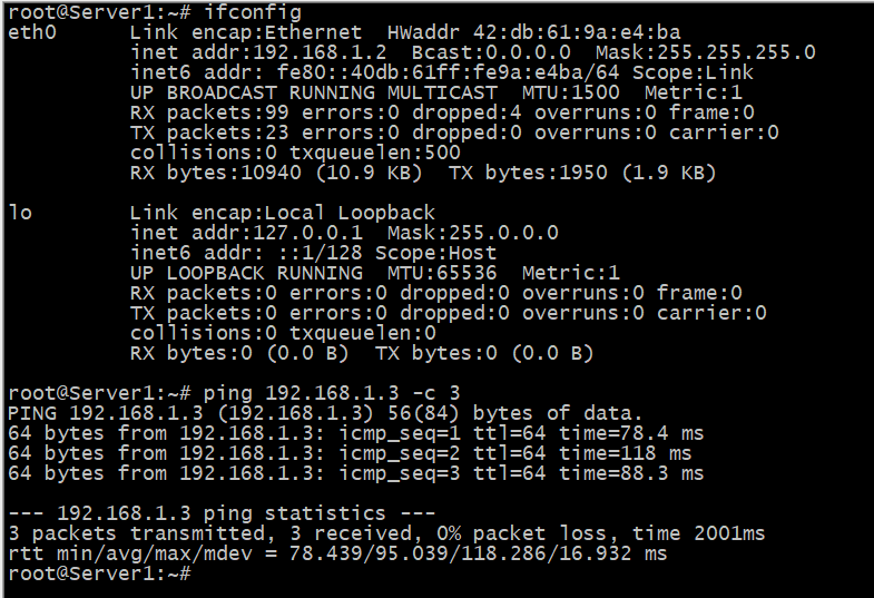
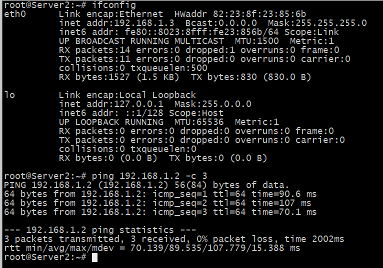
Kita harus merubah IP address Server 1 dan Server 2 menjadi satu segment karena konfigurasi VXLAN pada artikel ini hanya Bridging bukan Routing.
Server 1
Server 2
Network Telco Engineer – SDN/NFV Enthusiast
Komentar